|
level
of difficulty |
beginner
|
intermediate |
advanced |
The Foamboard Octant project
Build
your own octant for celestial navigation
Sextants and Octants are similar instruments. Both measure angles and are used in celestial navigation. The sextant has this name because its scale is one sixth of the full circle ( 60 degrees ). The Octant scale is thinner: 1/8 of the circle or 45 degrees. The instrument optics are the same with a scale of two arc degrees per degree ( so the octant, with its 45 degree scale, can measure up to 90 degree angles)
Modern celestial navigation instruments are smaller than old ones. This shrinking was possible by precision optics and mechanics. In the old times, when instruments were made of wood, precision was obtained by increased sizes. For those large instruments, the octant design was more convenient than the sextant, because it is slender.
This DIY project is like those old octants. It is large in size, making it possible to read angles within a couple minutes.
|
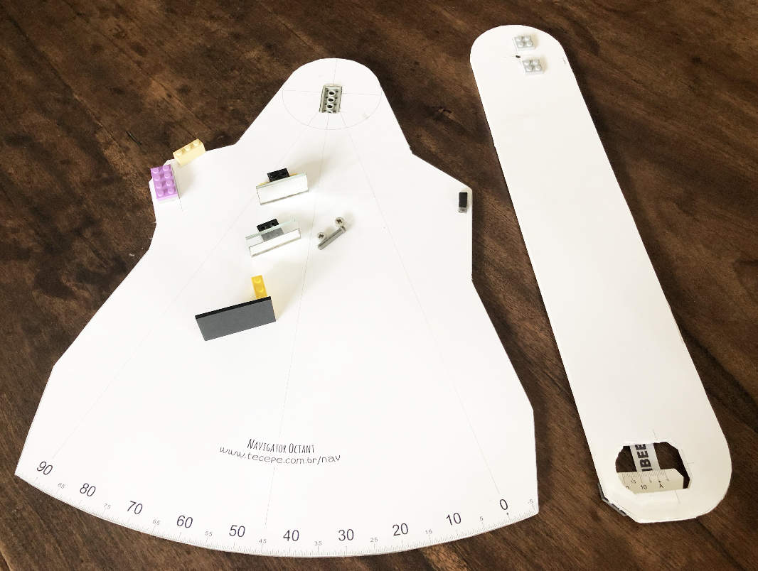 Octant parts |
The scale was originally designed to be printed in
A3 paper (297 x 420 mm), but it can also be printed
in A4 paper, if you don't have access to a wide paper printer.
Note that you loose precision when you
go smaller.
I actually used A3+ format paper, the widest my printer can handle. This is a little larger than A3.
A3+ is 329 x 483 mm and resulted in an octant of 37.5 cm of radius, which is large enough.
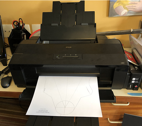
The base design consists of two large resolution PNG images, to be printed with 600 dpi resolution on ink jet or laser printers. A3 format is twice the size of regular office paper (A4).
|
Download Octant Images for printing:
|

Materials:
- 2 Foamboard 5 mm thick, large enough to mount a A3 size page
- 2 pages of heavy A3 premium presentation paper (around 150 g/m2)
- 2 mirrors rectangular 50 mm x 20 mm x 3mm thick
- 1 welder mask filter ( 5.5x11 cm shade #14 )
- Lego plastic axis and two nuts (see below)
- 2 shallow Lego bricks with axis holes ( to be embedded on the foam as axis)
- more Lego bricks for mounting mirrors and filter (see below)
- Epoxy glue two components ( 30 minute cure )
- Cyanoacrylate glue ( Super Bonder )
- Spray Mount adhesive ( to bond the printouts with minimum distortion )
- White glue for paper ( for bonding the Vernier scale )
- Paper cutter ( Olfa type )
- Steel Wool ( window cleaner )
- Scissors, square ruler, ruler, paper clips, adhesive tape, sand paper #200...
The instrument frame and arm are made of foamboard.
Foamboard is basically a paper sandwich
with foam in between. It is commonly used for the mounting of prints and photographs and as backing in picture frames. It's about 5 mm thick and
that gives it a relatively solid structure and flatness.
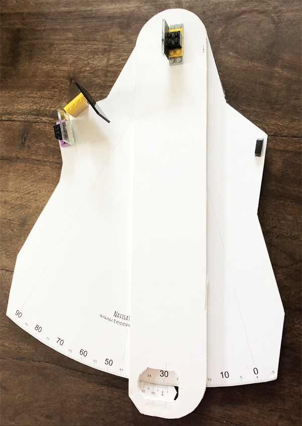
anatomic design
Note that this material will not stand either rough handling or moisture. There are other kinds of plastic and wood boards that could be used to build a more resistent instrument. You are encouraged to do that. I went with foamboard because I had it around and it is so easy to cut. Very light too. But fragile.
The instrument frame and arm images were printed on premium presentation paper ( density 145 g/m2 ) which is heavier and deforms less than regular paper. The design uses a minimum of printing ink, to reduce paper deformation while printing.
Also to minimize deformation while bonding the paper to the board, a spray mount adhesive was used. The scale must be bond completely flat to the board, without bubbles or wrinkles. Any visible deformation will ruin the instrument precision.
Printer precision check The scale image in this design was generated using formulas and is geometrically correct. What your printer will actually print is a different matter. I found modern printers can do a pretty good job. There are a couple checks you can do on your printed scale, to see if it is precise. Measure the radius R of the octant (distance from axis center to scale arc). Check the radius for 0, 45° and 90°. They must match. Measure the distance D between 0 tick and the center line of the instrument. This must be: D = R * Sin(22.5°) = R * 0.3827 For instance: if R=34.10 cm, D must be 13.05 cm The distance from 90° to the center line must be the same. If you have a navigation divider, you can measure arcs at one point of the scale and transport to a different point. Equal arcs must have the same length. |
 |
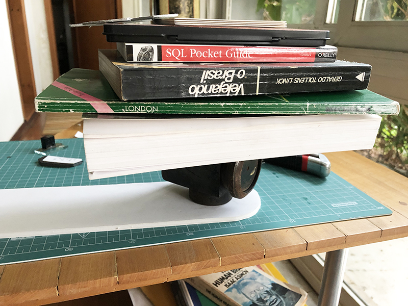
The spray adhesive is a relatively dry glue, but avoid wetting the paper with too much spray. Do the job outside and spray the paper in regular movements, until the whole page is covered. Allow the adhesive to dry a few seconds and paste the page to the foamboard in one forward movement. No removing and re-pasting allowed. If you mess up, print another scale. Press the page with a heavy book on a flat surface and allow it to dry for some time. |
With a sharp paper cutter, cut the frame and arm pieces . Cut the main scale arc very carefully. Smooth the arc foam with sand paper. Note that the main scale and arm scale (Vernier) must touch each other and the arm rotation must be smooth across the whole arc.
Also cut off the arm window.
The arm axis
==========
The arm axis setup must be sturdy and allow arm rotation, without slack. The foamboard itself is not capable of that (too soft), so I choose to use Lego pieces with axis holes, which were embedded to the foamboard.
| Since I will be using Lego pieces elsewhere
in this project, I'd like to say that I'm not associated or sponsored by Lego. |
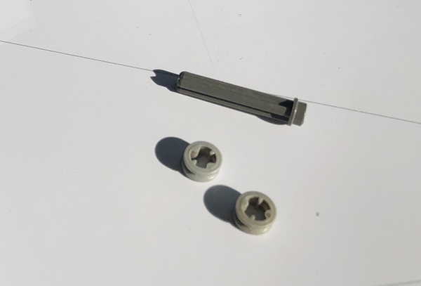
There are many kinds of Lego pieces that can be used to build a simple rotation axis. I choose two
shallow bricks with axis holes,
a small-headed short shaft and two nuts.
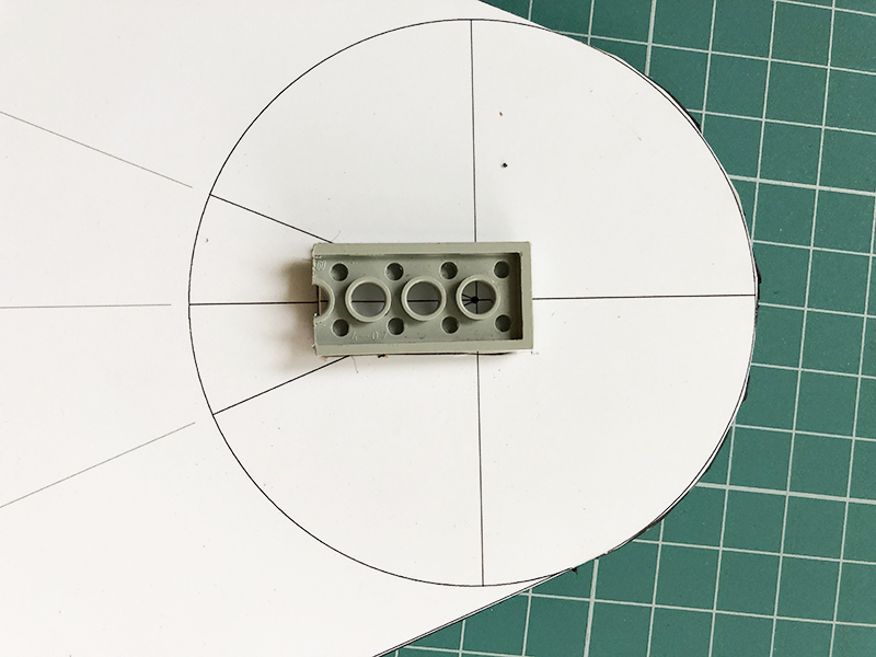
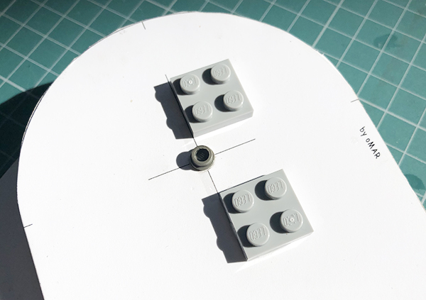
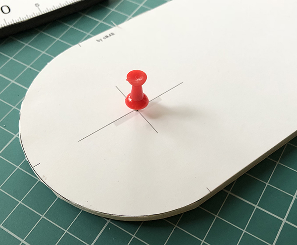 arm axis center marked with a pin |
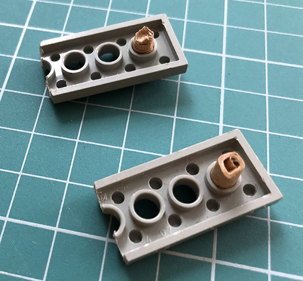 axis bricks with holes protected for bonding |
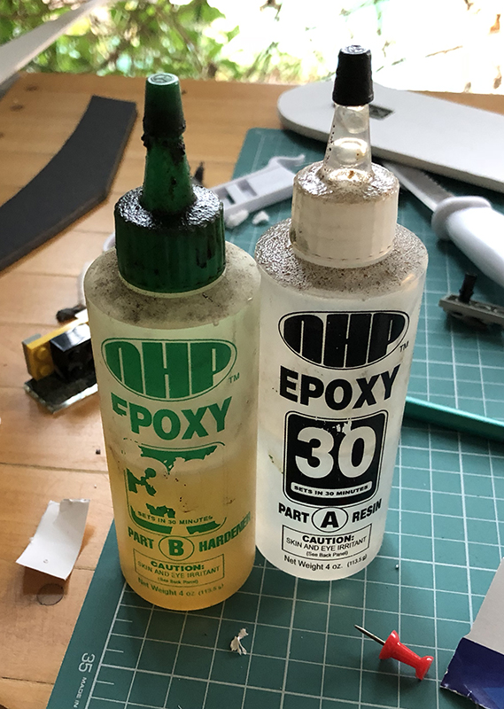 epoxy glue two components |
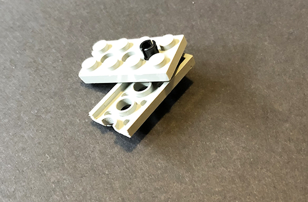 axis assembly ( In the end I used a different shaft ) |
The shallow bricks used are conveniently about the same thickness of the foamboard ( about 4 mm). The axis bricks were bonded to the foamboard with epoxy two component glue (30 minutes cure time). As it cures, the epoxy hardens and joints the brick and foamboard firmly. Any force the axis receives is distributed to the board evenly, to avoid axis displacement.
In preparation to the bonding operation, position the Lego brick over the frame so that the axis hole center coincides with the printed center. Trace the brick outline with a pencil.
Cut out the top layer of paper of the foamboard ( the rectangle to fit the Lego piece in ). Scratch the foam out, leaving only the bottom paper layer untouched.
In the Lego bricks, protect the axis hole to avoid epoxy contamination. I used adhesive tape rolls for that, fitted to the hole diameter ( 5 mm )
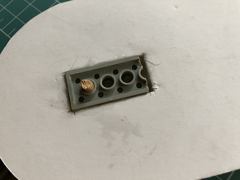
Arm axis detail, with brick bonded to the back of the foamboard
Mix a small quantity of the epoxy glue (equal parts of the two components), and drop it on the rectangular pool on the foamboard. Spread the glue evenly. Insert the brick, so that the piece and foamboard surfaces are about even. Clean up any epoxy that overflows.
Allow some 15 minutes for the epoxy to half-cure. Now hold the brick and gently remove the axis hole protection rolls, before they get too tightly attached to the epoxy. Make sure not to contaminate the axis hole with epoxy, or displace the brick while removing the roll.
Press the brick on a flat surface and allow the glue to cure for a couple hours.
Embed the other brick similarly to the front of the frame.
Mirrors
======
This octant has two 2 rectangular mirrors. This can be obtained and cut in any glass shop.
Both have the same size: 2 cm x 5 cm ( 3mm thick regular mirror )
Mirror is glass coated with a thin layer of reflective silver on one of the surfaces. Since the silver rusts in contact with air and humidity, it is covered with a protective epoxy layer (the back of the mirror)
 |
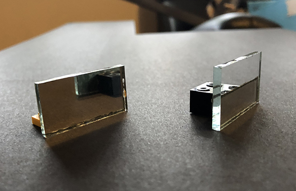
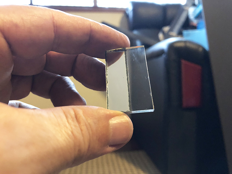
One of the mirrors in the octant must be half-silvered. It is the one fixed to the instrument frame. It combines the reflected image of the other mirror on the arm to the horizon image. This mirror is obtained by splitting it in two and removing the epoxy and silver layers on one side. Half of the mirror becomes regular glass. The other half remains a mirror. |
The protective epoxy is hard. I used the paper cutter blade for the removal job. With the blade point, make a longitudinal cut along the middle of the mirror. Then, with the blade inclined, gently scratch the epoxy out. It will come out as a fine powder. The glass itself is very hard and will not be easily spoiled. But avoid using the blade point on it, except for the center line. Use the blade edge inclined instead. After a couple minutes of scratching, you begin to see the silver under the vanishing epoxy.
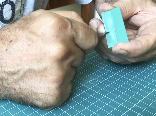
Once the epoxy is gone, use a steel wool ( window cleaner) to remove the silver.
After a while you have your new half silvered mirror.
To mount the mirrors to the frame and arm, they were bonded to regular sized Lego bricks (10mm thick). I used 2x2 bricks. For the semi-transparent mirror I had to cut out the 4 brick bumps ( because I could see their tips through the transparent part, which is also 10 mm )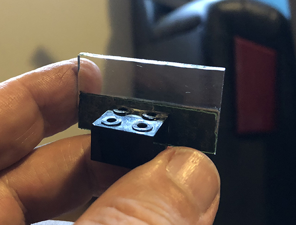
The mirrors were bonded to the bricks with cyanoacrylate glue ( Super Bonder ). Make sure the mirror and brick form a square angle. Use a square ruler face-to-face to the mirror, working on a flat surface, on the bond operation.
The mirror positions are marked on the printed scale and arm. The half-silvered mirror tower base is bonded to the frame, as seen in the image below ( to the right. On the left is the Sun filter assembly )
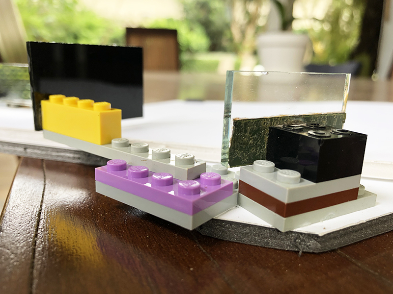
frame mirror and filter towers
Use 1 extra shallow brick on the frame mirror tower, so that both mirrors are at the same height in relation to instrument plane. The arm mirror tower, attached to the arm, is lower.
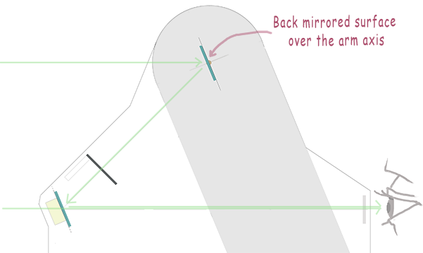
The arm mirror must be positioned so that its mirrored surface (i.e. the back of the mirror ) is over the center of the axis, and it pivots on that axis. In order to avoid interference between the instrument axis and the arm mirror, I chose a shaft with a small head.
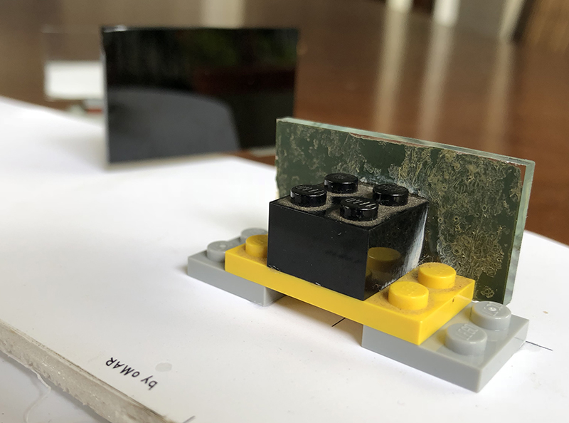
arm mirror tower
Octant optics with the angle set to zero
Arm shaft and mirror tower support bricks aligned
shaft and nuts
Bond the arm mirror tower base to the arm, using Super Bonder.
Position the small arm scale, also known as Vernier, in the arm window, underneath the arm piece. Do not bond it yet. This will be done last, after the mirrors are mounted, on the initial calibration. Fix it temporarily with paper clips.
Mount the arm and the frame using the shaft. Lock it with the two nuts. Make sure the arm can swing smoothly over the 90 degree range. Use fine sand paper to remove any bumps in the main scale arc.
Set the arm position to zero ( align the A tick in the Vernier with 0 tick in the main scale )
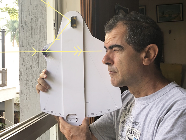
Now take a sight of a point located far away, at least a few hundred meters.
In this zero position, the two mirrors should be parallel. But there is probably a small error in this parallelism. Holding the instrument vertically and with the horizontal axis aiming to the chosen point, look through the frame mirror.
You will see the selected point directly and its reflected image on the arm mirror. Swing the arm gently so that the reflected and the direct
images are both at the same vertical altitude. Press the arm and frame together to freeze the arm in that position. Now bond the Vernier scale, so that the point A and scale 0 ticks match perfectly. I used white paper glue for that. Super Bonder is too fast for a precise positioning.
Vernier
=======
The Vernier is a kind of scale used before micrometer screws found in modern instruments. In the case of this octant, each degree of the main scale is divided in 3 parts, each 20 minutes of arc wide. The A tick in the Vernier points the measured angle.
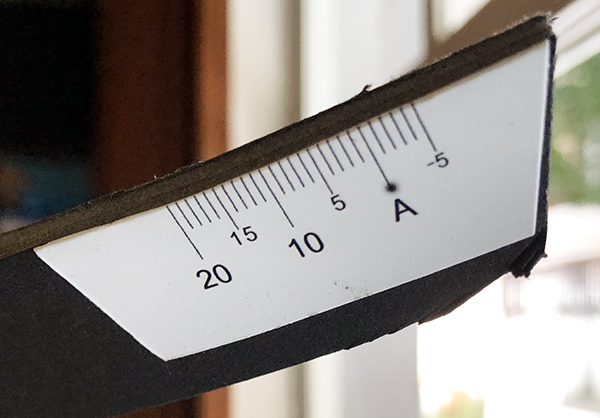
Arm scale (aka Vernier)
Reading Vernier scale
==================
When Vernier tick A is between two main scale ticks, the fraction of the 20 minutes must be estimated. The Vernier scale is 20 ticks wide. Find which of the ticks in the Vernier aligns with one on the main scale. This is a number between 0 and 19, and must be added to the main scale reading. For instance:
|
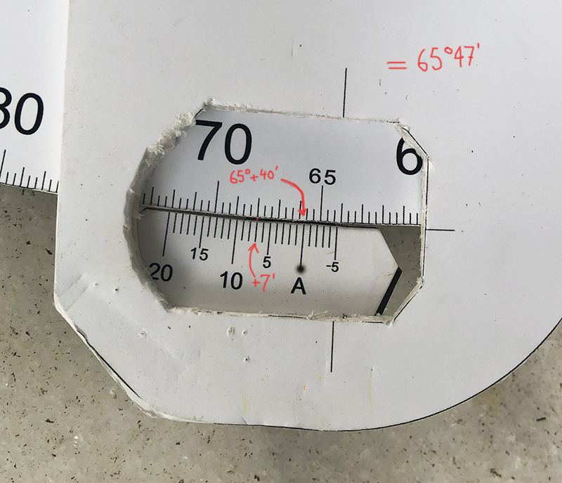
In reading 1 to the left, the main scale reads 65 degrees and point A is between the second and third tick inside that degree. So that's 40 minutes more. The ticks on the Vernier and main scale align at the 7th tick. That adds to 65 degrees and 47 minutes. |
|
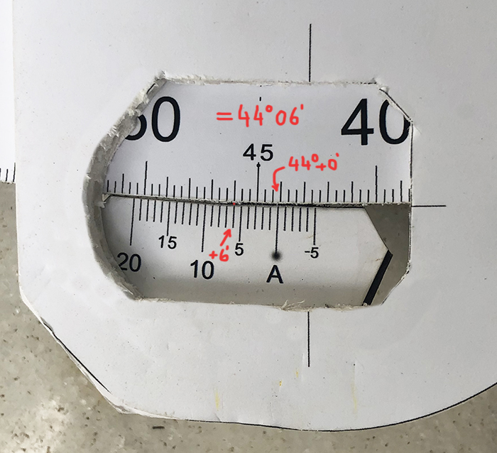
In reading 2, the main scale reads 44 degrees plus zero minutes. The Vernier 6th tick aligns with the main scale, so we have 44 deg and 06 minutes |
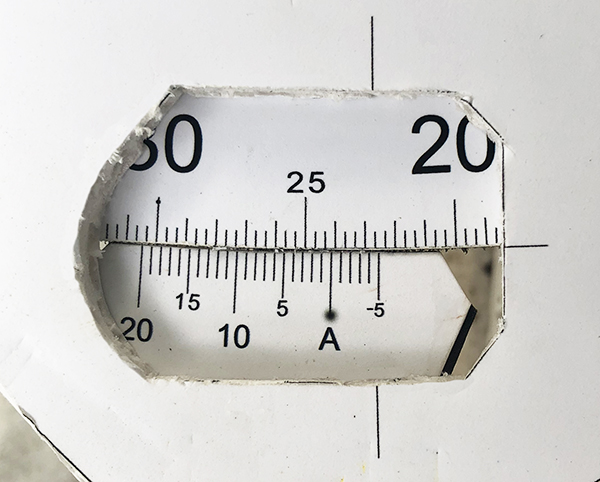 |
exercise: what is the reading ? |
 |
Sun filter: Protect your eye ! During the day, the only celestial objects that you can see are the Sun and - sometimes - the Moon. So it is nice to be able to use the octant observe the Sun. There is the problem of the intense light of the Sun, that can cause harm to the eye, if observed directly for even a short period. To remedy that, sextants have a bunch of dark filters that you can add to the line of sight, to filter out the dangerous Sun light. In this design, a welder mask glass was used (ask in construction shops for shade #14) . This is a very dark filter, safe for Sun observation. It costs about one dollar. The filter must be located between the two mirrors and cover the arm mirror completely. It must be positioned perpendicular to the light ray. See the frame plan. Note: This Nasa site suggests that, for eye safety, one should use at least welder shade number 12 (#14 is even better). The text focuses on eclipse observations, which are particularly dangerous because people stare at the Sun for a long period in those events. https://eclipse2017.nasa.gov/safetyThis page reviews materials for Sun filters and its safety, including welder glass #14: https://www.rasc.ca/tov/safetyOther Sun safety tips:
The welder glass filter comes in a rectangular shape of 11cm x 5.5 cm . I had mine cut in the glass shop, a bit larger than the mirrors, with 5.5 cm x 3 cm. Note that the filter placement must not interfere with the movement of the arm between 0 and 90 degrees. The arm has to have room to move underneath the filter. The filter cannot be too far from the arm either, or the Sun light reflected will pass between the arm and filter and hit your eye. Since the filter is mounted with Lego bricks, it is removable for observing other stuff than the Sun. Only the large base brick is bonded.
|
 plastic spring pressing the arm and frame together |
As a finishing touch, I added a spring made of plastic card. It presses the arm to the frame, so that the main scale and Vernier are levelled. |
foamboard octant optics
Other DIY projects:
|


xxx-xxx
- published dec-18 by Omar Reis
- jan19: Om: changed welder glass spec from #12 to #14. See eye security notes
©Copr 92-2012 Omar F. Reis - All rights reserved